
Restraint control module что это
Обновлено: 18.05.2024
Air Bag Supplemental Restraint System (SRS) (Description and Operation)
The air bag supplemental restraint system (SRS) is designed to provide increased collision protection for front seat occupants in addition to that provided by the three-point safety belt system. Safety belt use is necessary to obtain the best occupant protection and to receive the full advantages of the SRS.
The air bag supplemental restraint system (SRS) components are shown in the following illustration.
Air Bag Supplemental Restraint System (SRS) Components
Driver Air Bag Module
The driver air bag module:
- is installed as an assembly.
- is mounted in the center of the steering wheel.
Clockspring
- is mounted on the steering column, behind the steering wheel.
- provides a continuous electrical path from the restraints control module (RCM) to the driver air bag.
Passenger Air Bag Module
The passenger air bag module:
- is installed as an assembly.
- is mounted in the RH side of the instrument panel.
Restraints Control Module (RCM)
The restraints control module (RCM) performs the following functions:
- signals the inflators to deploy the air bags in the event of a deployable crash.
- monitors the air bag supplemental restraint system (SRS) for faults.
- illuminates the air bag indicator if a fault is detected.
- flashes the air bag indicator to indicate the lamp fault code (LFC) detected.
- communicates through the data link connector (DLC) the current or historical diagnostic trouble codes (DTCs).
- signals the generic electronic module (GEM) to activate a chime if the air bag indicator is not available and another SRS fault exists.
NOTE: The safing sensor is internal to the RCM and is not repaired separately.
The RCM monitors the SRS for possible faults. If a fault is detected while the ignition switch is in the RUN position, the RCM will illuminate the air bag indicator located in the instrument cluster.
When the ignition is cycled (turned off and then on), the air bag indicator will begin its prove out sequence. During prove out the air bag indicator will illuminate for six seconds, go off for two seconds and then, if a system fault exists, flash the two-digit LFC. The air bag indicator will flash the LFC five times, then it will remain illuminated for the rest of the key cycle. The RCM will also communicate the current and historical DTCs through the DLC, using a scan tool. If the air bag indicator does not function, and the system detects a fault condition, the RCM will signal the GEM to activate an audible chime. The chime is a series of five sets of five tone bursts. If the chime is heard, the SRS and the air bag indicator require repair.
LFCs are prioritized. If two or more faults occur at the same time, the fault having the highest priority will be displayed. After that fault has been corrected, the next highest priority fault will be displayed.
The RCM includes a backup power supply. This feature provides sufficient backup power to deploy the air bags in the event that the ignition circuit is damaged in a collision before the safing and air bag sensors determine that deployment is required. The backup power supply will deplete its stored energy approximately one minute after the battery ground cable is disconnected.
Electrical System
The electrical system that supports the air bag supplemental restraint system (SRS):
- is powered from the battery through the ignition circuit.
- provides the electrical path from the restraints control module (RCM) to the air bag modules.
- provides the electrical path from the RCM to the air bag indicator.
- provides the electrical path from the RCM to the data link connector (DLC).
- provides the electrical path from the RCM to the generic electronic module (GEM).
Sensor
WARNING: The restraints control module (RCM) orientation is critical for proper system operation. If a vehicle equipped with an air bag supplemental restraint system (SRS) has been involved in a collision in which the center tunnel area has been damaged, inspect the mounting and bracket for deformation. If damaged, the RCM must be replaced whether or not the air bags have deployed. In addition, make sure the area of the RCM mounting is restored to its original condition.
The SRS contains two sensors which are integral to the RCM. The RCM is mounted on the center tunnel under the instrument panel.
Пройдена компания 4S607 — RESTRAINTS CONTROL MODULE REPLACEMENT

Получил я письмо от Ford Sollers с уведомлением о проведении сервисных процедур по замене на моем авто модуля управления удерживающей системой подушек безопасности и ремней безопасности — 4S607 — RESTRAINTS CONTROL MODULE REPLACEMENT = ЗАМЕНА МОДУЛЯ УПРАВЛЕНИЯ УДЕРЖИВАЮЩЕЙ СИСТЕМОЙ ПОДУШЕК И РЕМНЕЙ БЕЗОПАСНОСТИ
Скрин из Etis по отзывной

В пятницу пригнал авто к дилеру "Автопассаж" на Тульской и был приятно удивлен)) когда мне сказали что под мою комплектацию модуль на складе и мне его сразу поменяют и машинку я сегодня же и заберу)))
При замене не присутствовал, т.к. нужно было съездить по делам и машинку ремонтировали без моего чуткого присмотра))) ну да ладно)) главное у ОД есть ответственные люди, которые этот процесс контролировали))))
Описание процесса замены стырил с ффклуба)))
Порядок:
1) Принятие машины, мойка — при необходимости
2) Подключение IDS к авто
3) Запуск процедуры по замене модуля RCM
4) Выкл. зажигание
5) Разбор напольной консоли (верхняя часть и боковая водительская)
6) Снятие 2-х разъемов с модуля RCM и откручивание 3х винтов
7) С помощью определённых известных слов просовывание руки в доступные щели и через минут 5 модуль извлекается из консоли ((( (ручник тянуть из всех сил вверх, либо разборка всей напольной консоли до пола !)
8) Установка нового модуля (3 винта), подключение к нему обратно 2-х разъемов
9) Подключение и запуск IDS на обновление версии калибровки модуля RCM (на приборке мигает подушка безопасности)
10) После обновления калибровки на приборке гаснет индикация подушки безопасности
11) Запуск процедуры по активации новых датчиков продольного и поперечного ускорения, штатные с завода отключаются и активируются новые которые в новом модуле RCM.
12) Запуск процедуры по калибровке новых датчиков продольного и поперечного ускорения. Кузов авто должен быть в покое!
13) Запуск процедуры трогания в гору.
14) Очистка DTC, считывание что нет новых DTC
15) На приборке убеждаемся что нет активных индикаций а также что ноль предупреждений
16) Сборка напольной консоли в обратной последовательности
Конец.
При сдаче авто в ремонт был выписан заказ наряд на проведении ремонтных работ, по окончании правда ни чего не выдают, т.к. замена гарантийная и везде где необходимо отметки по замене стоят, а в случае необходимости иметь на руках заключение о гарантийной замене, надо было писать заявление на имя ГД дилера.
Модули Ford Focus 3

Модули ford focus 3 работают на трех разных шинах:
— Высокоскоростная шина — HS CAN (High-Speed Controller Area Network)
— Среднескоростная шина — MS CAN (Medium-Speed Controller Area Network)
— Multi-Media шина — MM CAN (Multi-Media Controller Area Network)
BCM (Body Control Module) — блок управления системами кузова
IPS (Instrument Panel Cluster) — щиток приборов
PCM (Powertrain Control Module) — модуль управления силовым агрегатом
TCM (Transmission Control Module) — модуль управления коробкой передач
ABS (Anti-lock braking system) — модуль антиблокировочной системы тормозов
RCM (Restraint Control Module) — модуль управления удерживающей системой подушек и ремней безопасности
HVAC (Heating, Air Conditioning, and Refrigeration) -модуль управления обогревом, вентиляцией и кондиционированием воздуха
FCDIM (Front Display Interface Module) — модуль интерфейса передних органов управления/дисплея
ACM (Audio Control Module) — передний модуль управления аудиосистемой
SRM (Speech Recognition Module) — модуль Bluetooth
Ford Focus Service Manual: Restraints Control Module (RCM)

WARNING: If a vehicle
has been in a crash, inspect the restraints control module (RCM) and the impact sensor (if equipped) mounting areas for deformation. If damaged, restore the mounting areas to the original production configuration. A new RCM and sensors must be installed whether or not the airbags have deployed. Failure to follow these instructions may result in serious personal injury or death in a crash.
WARNING: Do not
handle, move or change the original horizontal mounting position of the restraints control module (RCM) while the RCM is connected and the ignition switch is ON. Failure to follow this instruction may result in the accidental deployment of the Safety Canopy and cause serious personal injury or death.
The air bag warning indicator illuminates when the correct Restraints Control Module (RCM) fuse is removed and the ignition is ON.
The Supplemental Restraint System (SRS) must be fully operational and free of faults before releasing the vehicle to the customer.
Carrying out Programmable Module Installation (PMI) will not enable the 911 assist option that is disabled. The RCM and Accessory Protocol Interface Module (APIM) must be configured correctly to fully support 911 assist functionality.
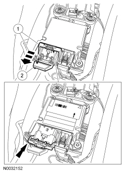
- Disconnect the small RCM electrical connector.
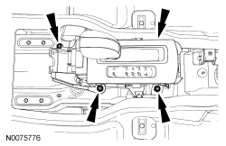
- If equipped with an automatic transmission, remove the 4 nuts and position the gear selector aside.
Installation
-
WARNING: Always
tighten the fasteners of the restraints control module (RCM) and impact sensor (if equipped) to the specified torque. Failure to do so may result in incorrect restraint system operation, which increases the risk of personal injury or death in a crash.
Install the RCM and 3 bolts.
- Tighten to 11 Nm (97 lb-in).
- If equipped with an automatic transmission, install the gear selector and 4 nuts.
- Tighten to 9 Nm (80 lb-in).
- Connect the small RCM electrical connector.
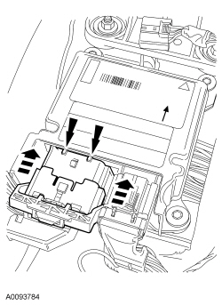
- Make sure the large RCM electrical connector position assurance lever is in the FULL RELEASE position before attempting to connect the connector.
- NOTICE: Placing the large Restraints Control Module (RCM) electrical wiring connector into the RCM at an angle can cause bad electrical connections and damage components.
Position the large RCM electrical wiring connector into the RCM .
-
NOTICE: Do not push the connector to where the lever pivots and seats itself. Light pressure is needed to get the connector into position on the Restraints Control Module (RCM) before using the lever to fully seat the connector.
With the large RCM electrical wiring connector uniformly aligned to the RCM , lightly push in until a subtle audible click is heard and a slight resistance is felt.
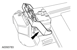
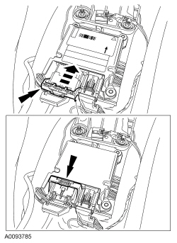
- Connect the large RCM electrical wiring connector.
- Using the connector position assurance lever, pivot it toward the RCM , drawing the connector into the RCM .
- Make sure the thumb tab is engaged to the retainer on the RCM and locked in place.
- Using the connector position assurance lever, pivot it toward the RCM , drawing the connector into the RCM .
- Install the center console. For additional information, refer to Section 501-12.
![]()
Restraints Control

![]()
Front Impact Severity Sensor
Item Part Number Description 1 W712191 Front impact severity sensor bolt 2 14B006 Front impact severity sensor 3 — Front im .

More about Ford Focus:
Ford Focus Connecting Rod Cleaning
NOTICE: Do not use a caustic cleaning solution or damage to connecting rods can occur. NOTE: The connecting rod large end is a matched set. The connecting rod cap must be installed on the original connecting rod in the original position. Do not reverse the cap. Parts are not interchange .
Читайте также: