Что такое collapse piston rings
Обновлено: 15.05.2024

Всем доброго времени суток, кипил ДВС с небольшим жором масла.
Перед установкой хочу поменять кольца и МСК, теперь стает вопрос, какие кольца ставить.
Однозначно буду ставить кольца типа Cr (Наборные) и очень хочется что бы они были стальные.
Искал HASTINGS PISTON RING — 2C4573, но к сожалению их нет в наличии не у кого.
Есть в наличии
NE — 9074800 (На M54B30)
MAHLE — 081RS001010N0 (На M54B30)
Kolbenschmidt — 800050810000 (На N42B20)
Из всего предоставленного хочется Kolbenschmidt но они на ДВС N42 (на сколько помниться цилиндры никасиловые у этого ДВС)
This post is part of the series: Inspection - Marine Engine Parts
Inspection is an important duty to be carried out on Engines after regular intervals in order to keep the engines in safe working conditions. This series will help you in carrying out the inspection on various marine engine parts.
Piston Ring Material
The piston rings are made of fine-grained alloy cast iron. This material possesses excellent heat and wear-resisting quantities inherent in its graphitic structure.
The elasticity of this material is also enough to impart radial expansion and compression which is required for assembly and removal of the ring, and especially to enable it to exercise flexible pressure on the cylinder walls.
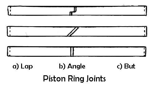
The piston rings are split so that they can be expanded and slipped over the piston head and into the recessed grooves cut in the piston. The rings usually have butt joints, but in some heavy-duty engines, the joint may be angled, lapped, or of the sealed type.
The outer diameter of the ring is somewhat larger than the cylinder bore and the split point is open. When it is installed, it is compressed thus giving it an initial tension, the joint is nearly closed. When in position, it pressed tightly against the cylinder wall.
Ring Coating
To prevent rapid wear, various coatings are used on the compression rings. The coating also affects wear-in. The term wear-in means rapid removal of irregularities of new rings. When new, the rings and cylinder wall have certain irregularities and do not fit perfectly, however, after some time, these irregularities are worn away so that a much better fit is obtained.
Relatively soft substances such as graphite, phosphate and iron oxide, which wear rapidly, are often used to coat the rings and thus help this wear-in. The rate of wear in the cylinder bore can be considerably reduced by chromium-plating the top ring rather than the bore. A chrome-plated ring, however, must not be used in conjunction with a plated bore or hardened linear.
Ring coating also has good oil-absorbing properties. They “soak-up” some oil, thus improving ring lubrication. The coatings also tend to prevent ring scuffing. The scuffing results from metal to metal contact, high local temperatures, and actual small area welding of the ring and cylinder wall metal.
Although the weld breaks by further movement of the piston but scratches are left. The coating prevents such scuffing because a weld cannot take place unless there is actual iron to iron contact.
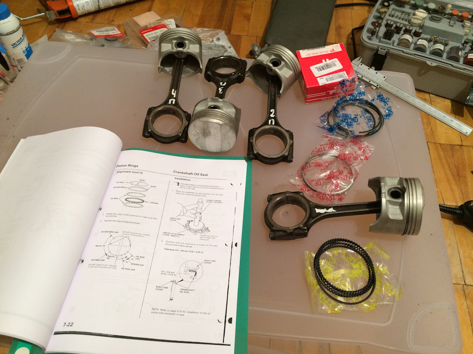
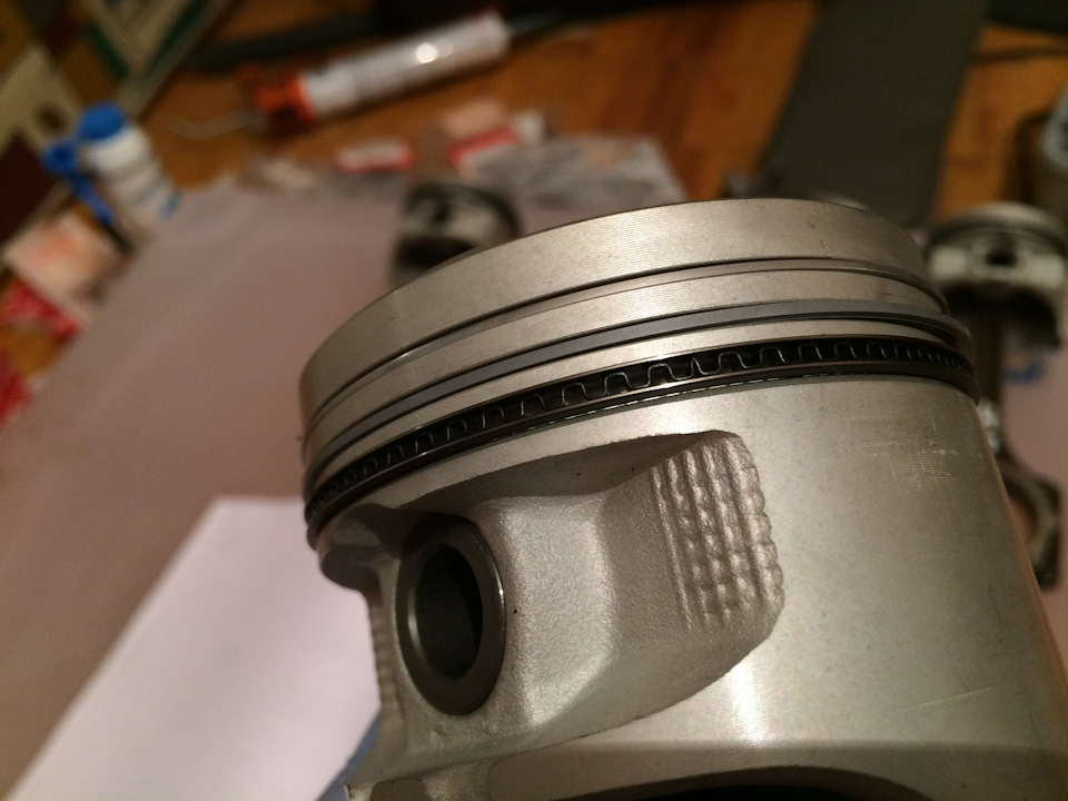
Установил поршневые кольца

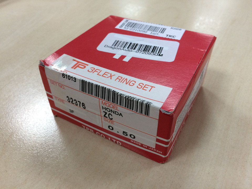
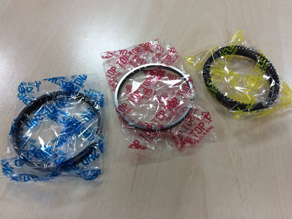
Получил кольца, которые хотел и приступил с постепенной сборке. На самом деле проводил опрос у народа, оказалось, что народный выбор — это TP. Вот они у будут установлены. Но найти их было не совсем просто, два разных магазина принимали мой заказ и привозили мне кольца Rikken вместо TP.
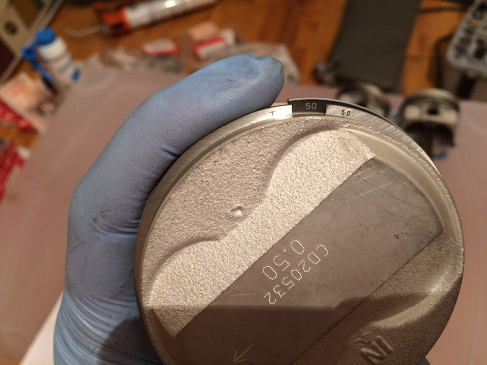
Teikoku Piston Rings, они же TP, они же TPR — код 32376.
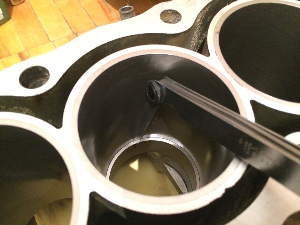
Перед установкой конечно же прочитал мануал и сделал элементарные замеры зазоров
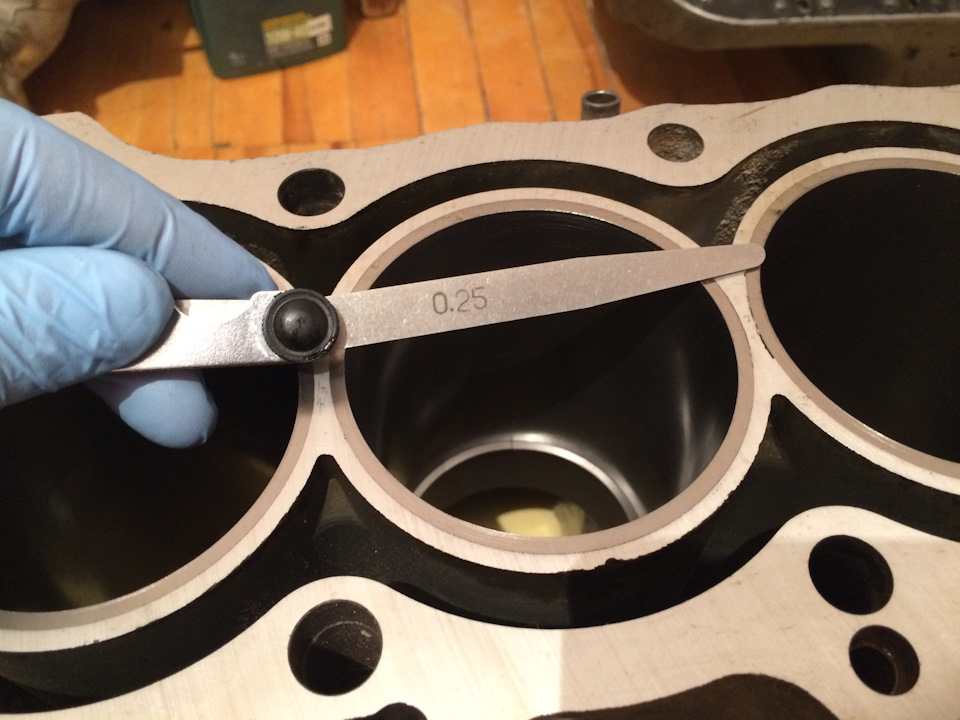
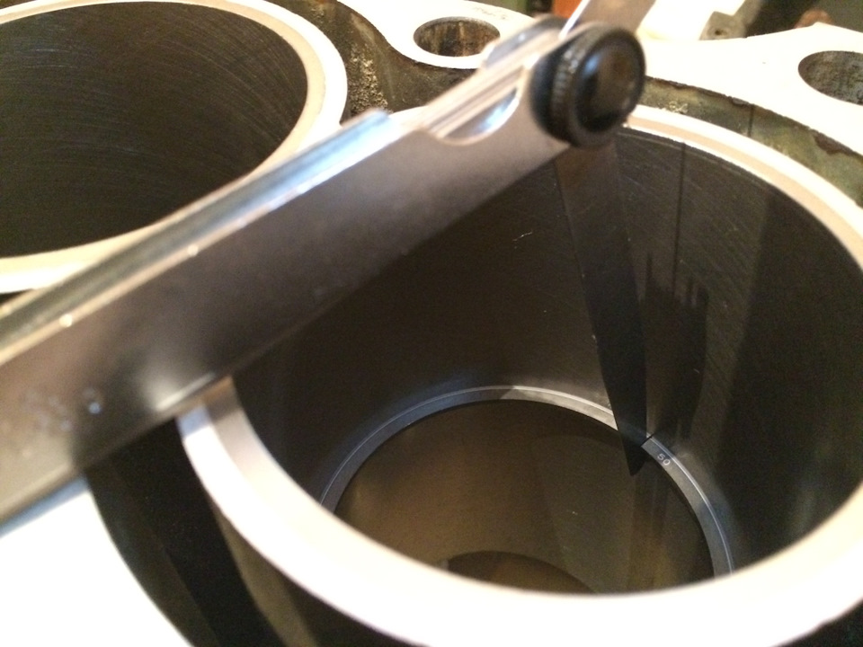
По спецификации зазоры должны быть следующими:
Верхнее кольцо — 0.15 — 0.30 мм
Второе кольцо — 0.30 — 0.45 мм
Маслосъемное кольцо — 0.20 — 0.70 мм
У меня зазоры на первом кольце 0.25 мм, на втором 0.35 мм. Маслосъемные не замерял, но думаю, что тоже в пределах допустимого.
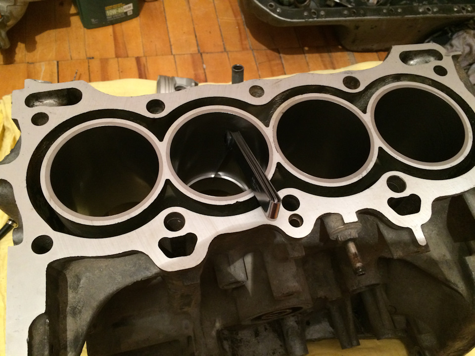
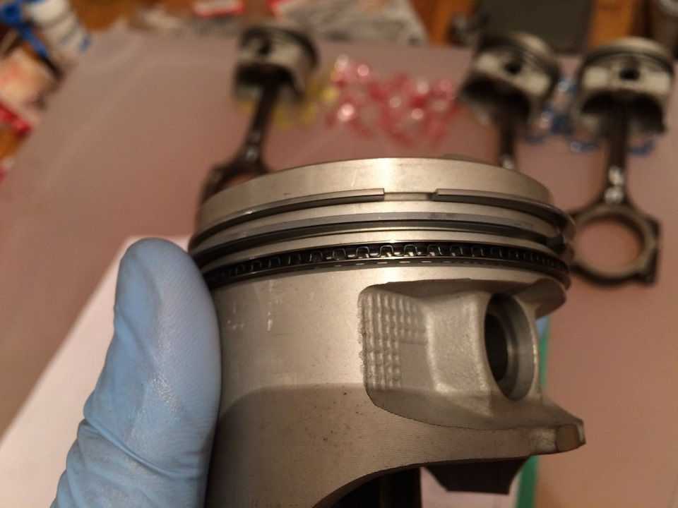
Ну и дело пошло дальше, все по инструкции
Об ориентации маслосъемного спейсера в инструкции ничего не сказано, поэтому направил замок вверх, как было на старых поршнях.
Это уже все 4 поршня готовы

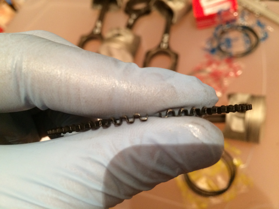
Так же в инструкции ничего не сказано об ориентации самих маслосъемных колец. И на них нет никаких пометок. Скорее всего их можно одевать как угодно. Но я смотрел несколько видеороликов на ютубе (там вазовский мотор собирали) и там было сказано, что направление маслосъемного кольца определяется путем его сдавливания, в результате кольцо постоянно прогибается только в одну сторону. Кто что зает об этом?
Piston Ring Gap [Clearance Measurement]
Piston rings have a gap so that they may be installed into the piston grooves and removed when worn out by expanding them. The gap ensures radial pressure against the cylinder wall thus having an effective seal to prevent leakage of heavy combustion pressure.
Wear in the piston ring grooves makes the rings rise and fall throughout the movement of the piston, so creating a pumping action and resulting in heavy oil consumption. Excessive gas blow-by, loss of compression will also take place if this gap is too much.
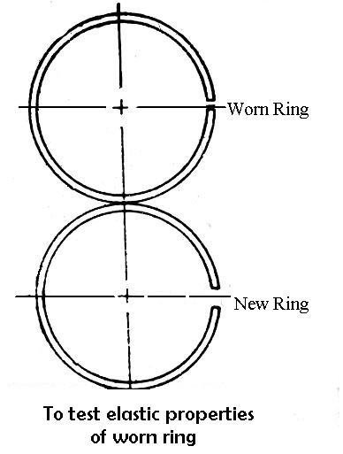
During service, the piston ring may have lost some of its elastic properties due to which radial pressure will be reduced on the cylinder wall. This property can be checked by pressing together worn and a new ring, as in figure and observing whether the gap of the worn ring closes more than the new ring.
How to Remove & Fit the Piston rings?
The piston rings should be carefully removed from the piston either with a special removal and installation tool or with three brass strips. The tool expands the ring so that it may be easily removed from the piston. In the latter case, three strips are spaced around the circumference of the piston and the rings are fitted over them.
The strips can be withdrawn and the ring is dropped into the groove. Ring compressor is used to compress the rings for inserting it into the cylinder while assembling the piston and cylinder. The gaps of the rings should not be in line, but they should be staggered so as to prevent the compression from having a direct path to leak by the piston skirt.
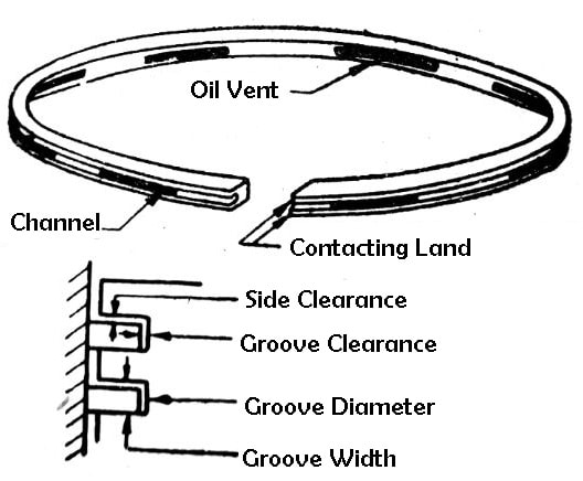
Clearances
Groove Clearances
Ring clearances are necessary to allow movements and thermal expansion. Axial clearance in the groove must be gauged to allow gas pressure to pass to and from the back of the rings. Circumferential clearance at the ring joint is necessary to allow for thermal expansion, but should not allow excessive blow-by of gases.
- Butt clearance should be maintained within this range of 0.4 - 0.5 % of cylinder bore.
- Should be as small as possible (as per maker’s instruction), but should never close completely.
- If the ring gap is too small, the ring may break due to the restriction on its thermal expansion when coming up to working temperature. Even if the ring remains intact too small a gap may also cause excessive pressure between the ring and liner surfaces. This can lead to liner scuffing due to the oil film breaking down; or at the least cause an increase in liner wear.
- It is essential for free movement during operation.
- Insufficient vertical clearance will cause rings to stick in the groove or break as they come up to operating temperature.
- To be kept minimum to avoid ring hammering and ring groove wear.
Required Properties
- Inherent Hardness for Wear Resistance- This will provide longer periods between piston ring replacement.
- Low Friction and Self Lubricating- both of these properties promote efficiency due to a reduction in fuel and lube-oil usage.
- Corrosion Resistant – one of the most important properties due to the heavy fuel oil being very corrosive because of its high sulfur content.
- Load Bearing – large forces and shock loads are produced in the internal combustion process; the rings must be robust resist these.
- Good Heat Transfer – the rings must readily transfer heat; also being resistant to the high temperature of combustion, whilst maintaining the other properties.
As well as the above properties the piston rings should have similar thermal expansion to that of the cylinder liner. This is required to maintain their optimum clearances both within their grooves and between them and liner.
Types of Piston Rings: Parts, Function, Material, Clearance [PDF]
In this article, you’ll learn what is piston ring, how it works in a piston? different types of piston rings with their functions, and more.
Also, you can download the PDF version of this article at the end of it.
Types of Piston Rings:
- Compression rings
- Counter bored and scraper rings
- Headland rings
- One-piece slotted cast iron type
- One-piece pressed steel type
- Three-piece steel rail type with an expander
Compression Piston Rings
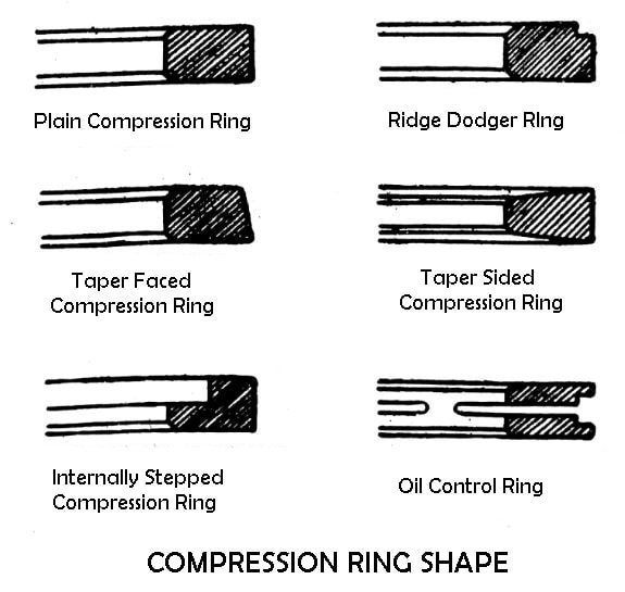
In modern engines, there are two or three compression rings fitted into the top grooves. The number of compression rings tends to improve the compression ratio. An oil control ring is fitted into the lower groove of the piston. Generally, the second and third compression rings are taper-faced and supplied to improve oil sealing.
![compression ring shape]()
Taper-sided compression rings are utilised to control ring-sticking problems in high output engines. It must not be fitted in grooves other than ones of the same section. A special ridge-dodger ring having a small step is specially designed for use in worn engines so that the wear ridge left by the original compression ring is cleared.
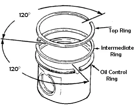
![Types of piston rings: compression rings]()
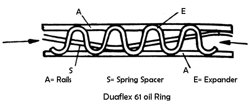
In many cases, oil control rings have a series of slots which transfer excess oil through holes in the piston groove to the inside of the piston and so to the sumps but leave sufficient oil to lubricate cylinder walls. Oil control rings slightly more radial pressure than compression rings.
![Duaflex 61 oil ring]()
Counter Bored and Scraper Rings
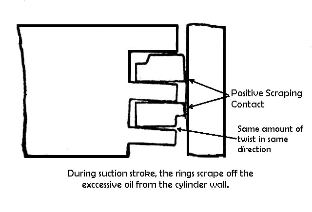
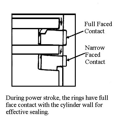
In many engines, these types of piston rings are used for the top and second compression ring. During suction stroke as shown in the figure, the rings twist slightly due to the internal forces produced by cutting away a corner of the rings.
![]()
Thus, as the rings move down they rub off the oil that has been left on the cylinder wall by the oil control rings. During the compression stroke when the rings move upward, they tend to skate over the oil film on the cylinder wall. Thus, less oil is sent up into the combustion chamber.
![]()
During power stroke as shown in the figure, the combustion pressure causes to untwist the rings, thus they have full-face contact with the cylinder walls for effective sealing. During the exhaust stroke, the same action takes place as in the compression stroke.
Headland Rings
Headland ring is a special type of compression rings, having L-shaped cross-section. It covers or shields the headland area of the piston. This is the area of the piston between the top ring groove and the head of the piston.
This area holds a certain amount of air-fuel mixture that does not burn because the cylinder wall and piston cool this air-fuel mixture below the combustion point. This unburned air-fuel mixture passes out of the engine and can produce smog.
![headland piston rings]()
By the use of headland ring on the piston of the special type having chamfered top, this space is eliminated so that the amount of unburned air-fuel mixture exhausted from the cylinder is reduced. This increases horsepower up to 10 %.
The headland ring also has the advantage of good sealing during the power stroke. As combustion starts, the pressure acts quickly on the upper lip of the ring, forcing out thus having good sealing with the cylinder wall.
Why Two Compression Rings?
Usually, two compression rings are installed on the piston. During the power stroke, the pressure increases as high as 70 kgf/cm2 and would be difficult for a single compression ring to hold this much pressure.
If there are two rings, this pressure will be divided between the two rings. The load on the upper ring is reduced so that it does not press quite so hard on the cylinder wall. Wearing of ring and cylinder is also reduced.
Oil Control Rings
Some connecting rods have an oil split hole which splits oils from the oil pan on the cylinder wall during each revolution of the crankpin. For more oil reaches on the cylinder wall that is needed. It must be scraped off and returned to the oil pin. Otherwise, it will go into the combustion chamber and burn.
This would increase oil consumption so that the engine would require the addition of oil at frequent intervals. Also, the burned oil would foul the spark plug, increase the possibility of knocking and hamper the action of compression rings.
Instead of having a cooling, sealing, cleaning, and lubricating effect on the cylinder walls, the oil must be removed from the cylinder wall every time so that it may not enter the combustion chamber. This is done by the oil control ring.
1. One Piece Slotted Cast Iron Type
These types of piston rings have slots between the upper and lower faces that carry on the cylinder wall. The oil scraped off the cylinder wall moves into the slots in the back of the oil ring grooves in a piston and from there it returns to the oil pan.
Some rings of this type are installed with expander rings. The expander spring increases the pressure of the ring on the cylinder wall which improves the oil scraping effect.
2. One Piece Pressed Steel Type
One-piece pressed steel type oil control ring mostly used in an engine with worn cylinder walls. It is made of pressed steel instead of cast iron. It can seal against only one side of the ring groove in the piston at a time, thus leaving an open path through which oil can pass upward toward the combustion chamber.
3. Three Piece Steel Rail Type with an Expander
In three-piece steel rail type oil control ring, the expander spring forces the rails not only upward into contact with cylinder walls but also upward and downward against the upper and lower sides of the ring grooves in the piston. This provides a more effective seal at these three vital points to provide effective oil control.
Why Only One Oil-Control Ring?
Usually, four-piston rings were installed on the long skirt pistons of earlier passenger car engines. The lower two rings were oil-control rings. But the use of lower hood lines reduced the number of rings to three.
Because two compression rings are necessary to withstand the high combustion pressure, hence there remains only one oil control ring. It is possible to use one oil-control ring because of manufacturing improvements and the more effective action of the modern oil-control ring.
Alloying, Machining and Plating
Ship’s two stroke marine diesel engine piston rings are cast from a base metal of pearlitic grey cast iron alloyed with varying percentages of molybdenum, chrome/vanadium, and nickel.
Modern engines use compact graphic cast iron alloyed with the typical elements as described earlier. However, a higher percentage of titanium and vanadium is now used to form hard carbides within the alloy structure.
The rings are cast using the “pot casting technique” that produces an oval casting from which the individual rings are machined and parted off, the edges being rounded automatically by the machine.
When I was serving my apprenticeship as a marine fitter in Harland and Wolff Belfast in the 1960’s, I spent a few months in the piston ring section of the engine-works department. Here the rings were machined by a device known as a “hurdy-gurdy” (probable Belfast colloquial term) this machine was right across from my workbench. It resembled a vertical lathe that could accurately machine the inside and outside of the casting; that was clamped in a large circular jawed vice.
Anyway, after machining and parting off the rings from the casting they came across to our benches where we de-burred them, leaving a ⅛“chamfer or round on their outer and inner edges. We then cut through the ring and passed them onto the next section where the gap was measured and very accurately cut to the required size. After this, the rings were trial fitted to the appropriate cylinder sized master gauge before being sent for grinding of the ring landing edges. The last operation was case hardening then the rings were sent to the engine assembly area for fitting to the pistons.
Nowadays the rings are machined using modern equipment; the rings cut, gap set and gagged open before being sent for tensioning and surface grinding of the landings. These surfaces along with the running surfaces are now chrome plated, the running surfaces being coated with a suitable running in compound such as aluminum, graphite or soft copper. A lot different from the old method; but I remember overhauling pistons when I was an engineer at sea, and sometimes there were burrs left on the machined edges of the new rings. These had to be removed before fitting as metal slivers could have broken away and scored the bore. This would never have been allowed in my day; maybe this is why Harland’s B & W engines were so reliable!
Piston Rings
What is Piston ring?
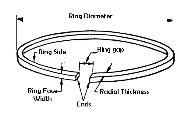
The piston rings are fixed into the grooves of the piston to maintain a good seal between the piston and the cylinder wall.
![Piston ring diagram]()
- To provide a pressure seal to prevent blow-by of burnt gases. Blow-by is the name that defines the exhaust of burnt gases from the combustion chamber, through the piston, and into the crankcase.
- To form the main path for conduction of heat from the piston crown to the cylinder walls.
- To control the flow of oil to the skirt and rings themselves inadequate quantity while preventing an excessive amount from reaching the combustion chamber with consequent waste and carbonization.
Piston Rings
![Piston Rings]()
In a ship’s main diesel engine the compression piston rings seal the piston against the liner, preventing leakage of the high temperature combustion gases.
Specially machined oil/scraper rings also play their part by removing the excess lubricating oil from the cylinders; helping to prevent an excessive build-up of carbon both around the rings and on the piston crown.
The next few sections examine their fabrication from casting to machining as well as the mechanical properties and design features of the modern engine piston rings; beginning with their required mechanical properties.
Piston Pin
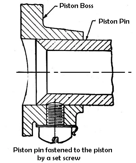
The piston pin connects the piston and the small end of the connecting rod. The piston pin is generally hollow and made from case hardened steel heat treated to produce a hard wear-resistant surface.
- The pin is fastened to the piston by set screws through the piston boss and has a bearing on the connecting rod, thus permitting the connecting rod end to swivel as required by the combined reciprocating and rotary motion of the piston and crankshaft. As shown in the figure.
![Piston pin]()
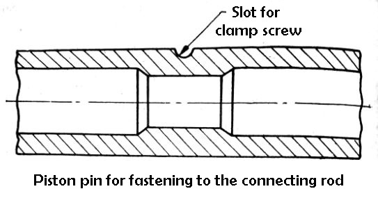
2. The pin is attached to the connecting rod with a clamp screw. In this case, the piston bosses form the bearing. A suitable slot is made on the circumference of the piston pin in which the clamp screw is fitted. As shown in the figure.
![piston pin for fastening to the connecting rod]()
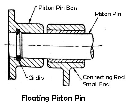
3. The pin floats in both the piston bosses and the small end of the connecting rod. It is prevented from coming in contact with the cylinder wall by two lock rings fitted in grooves in the outer end of the piston bosses, these rings are called circlips.
This method is now most generally used. In this case, a bushing of phosphor bronze or aluminum is used in the small end of the connecting rod. The bush develops very little wear and renewal only at long intervals.
![floating piston pin]()
Piston Pin Fitting
Piston pins may be selectively fitted and, if supplied with the piston, are not interchangeable. In very heavy alternate loading of the piston pins of compression ignition engines, special care is taken to avoid the risk of fatigue cracks.
The external bearing surface is finished to a very high degree of accuracy to ensure the correct fit in the piston and connecting rod. Piston pin should be inspected for wear, cracking, or pitting. circlips should always be renewed, and where soft end pads are fitted, check that they are not loose or cracked.
If you have still any doubts about the “Types of piston rings” you can contact us or ask in the comments.
We have also a Facebook community for you guys. If you like our article then please share it with your friends. Have any questions about any topic just feel free to ask in the comment section.
Finally, subscribe to our newsletter to get notified when we upload new articles.
References
- Sintercast: Compacted Graphite Iron for High Performance Piston Rngs
- Willie Scott: Breakdown at Sea (Removal of Piston)
- Mandiesel; Recommended piston ring inspection frequency and clearances for MAN main engines (Pages 13 through 16)
- Hprings: Piston Rings for Marine Diesel Engines
Design Factors and Sealing Requirements.
- Piston ring and liner surface operating temperature.
- Piston ring and cylinder liner machined surface finish.
- Medium used in piston cooling i.e. water or oil.
- Piston rings should operate at all temperatures with minimum lubrication.
- Piston rings should move freely in the groove.
- Piston rings, their groove, and cylinder wall should maintain their designed shape under high operating temperature and pressures.
- Must have inherent strength to withstand high shock loads due to compression forces.
Inspection Techniques
Piston rings can be easily and regularly examined for scuffing/burn evidence or ring breaks through the scavenge ports. Visual inspection of the size of the chamfer or rounding of the ring edges can also be used as a guide to wear, by comparing this with the size of the rounding on a new ring.
To enable this in-situ inspection, the engine turning gear is engaged to lower the piston just above bottom dead centre, allowing some of the ring set to be observed through the scavenge ports. Scuffing or burning is also a visual examination carried out using a torch. Checking for broken rings is carried out by pushing a piece of wood such as a broom handle (I used the shaft of a 2lb hammer) against each ring in turn. They should spring back to position against the liner; if they don’t - a broken ring is a 99% certainty. All of the rings can be examined by raising or lowering the piston for access and inspection through the ports. A sketch of this method is shown below; please click on image to enlarge.
I sailed on a ship which had a Werkspoor 2-stroke main engine that broke piston rings on a regular basis, and I used the above method for inspection of the rings. The bottom part of the cylinder liner was in two halves and contained the scavenge ports. This section was easily split to reveal a full set of rings and the means to replace broken ones. I never did find the reason for the ring breaking, but suspected misalignment between the bottom section and the rest of the liner although these components were doweled, I wonder if they ever found the reason.
Enough of my rambling; a trait of an old Irish retired marine engineer, so back to the present. For a thorough ring inspection to be carried out, it is necessary to remove the piston from the liner, a sketch of this is shown below; please click on the image to enlarge.
Once the piston is on the inspection stool, the ring inspection can be carried out and the following conditions may be evident on the rings.
- Running surfaces will be bright.
- Rings can be moved freely within their grooves.
- Not unduly worn, (measurement required) and should exhibit a good lubrication supply.
- Edges will still have a relatively sharp chamfer-without any signs of indentations or burn mark.
2. Micro or Macro-Seizures/Scuffing
- Dull running surface.
- Scuffing-Appearance of vertical strip/sharp burn marks
- Due to hard abrasive particle breaking from a badly machined ring or from particles entering cylinder via fuel.
- Thick and hard deposits of carbon preventing the rings from moving freely in its grooves; caused by lack of sealing, i.e. combustion gas being blown past.
- Blackish appearance
- Black dry zones on upper part of liner wall.
As the ship’s engineer gains experience it will become second nature to examine the rings and spot any of the above conditions at the regular inspections or on re-assembly after a breakdown.
Читайте также: