
Sega mega drive 1 rgb scart схема
Обновлено: 08.07.2024
Game Console RGB SCART Cable Diagrams
For anyone unfamiliar with what RGB video is see this Video Primer.
SCART pinouts and signal info can be found here.
SCART (aka Peritel or Euroconnector) cables for home video game consoles aren't standard, they are different for each console. The manufacturers have taken full advantage of this and, in what I assume is an effort to save a few cents, often place necessary components (esp. coupling capacitors) of the RGB output circuit inside the SCART cable. Since only a small fraction of people who own a console use/require a SCART cable it slightly reduces the overall cost.
This page contains circuit diagrams to aid anybody wanting build/repair/adapt these cables, as well as pinouts and a short description of the RGB video output (75 ohm driver) circuit. Enjoy.
TVs with SCART inputs are only common in Europe and Australia (mainly because we share a similar TV standard (thus TV designs) with most of Europe and the TV manufactures just leave the connectors in place). If you are from a somewhere where TVs with SCART inputs are rare then don't despair, some of the upper market TVs offer RGB input in the form of 4 phono sockets, one for each colour and one for composite sync. If such a TV can't be found for a reasonable price, then look around for an old RGB computer monitor that is compatible with the TV horizontal scan frequency, such as the commodore 1084 monitor. Alternatively, if a suitable monitor can't be located and you're good with electronics, then consider building a SCART to arcade monitor adapter.
The SCART spec states that to switch to RGB mode the CVBS Status pin must be fed 12V and the RGB Status (aka Fast Blanking) pin be fed 1-3V. Some games consoles only output 5V which may or may not be adequate. If the TV doesn't switch and there is no way to manually force a 'video mode' (such as a button on the remote control) then an external 12V supply may be required. In cases where the TV is a widescreen model or has a widescreen mode feature, applying only 5v to the RGB Status pin may force the TV into 16:9 widescreen mode.
In the diagrams I have drawn all the SCART ground pins connected together. This isn't required but it's a good idea to connect to at least two ground pins (usually 17 and 18). If you're using mini-coax to connect the RGB video (recommended if the cable is going to be long) then ground pins 5, 9 and 13 provide handy places to solder the shield. The reverse applies to the console end of the cable. I've only drawn one ground connection but it may be a good idea make use of other ground connections (if there are any).
Cables which run video and audio signals together without a seperating shield around the audio wires may cause an annoying 50 or 60hz buzzing sound in the audio which vaires in volume with the picture content. This is caused by the capacitive coupling of the two wires running next to each other. The longer the cable is the more capacitance between the wire. The best way to avoid this is to run a seperate cables for audio and video join them together again at the SCART end.

Connector is a 10 pin mini-DIN type. While it's a standard connector, it's extremely rare so don't expect to be able to buy one from the local electronics shop (or anywhere for that matter). The Saturn puts out luma/chroma (s-video) as well as the usual RGB/CVBS. Pinouts: 1 composite sync, 2 audio right, 3 audio left, 4 +5V DC, 5 red video, 6 green video, 7 blue video, 8 composite video, 9 luminance, 10 chrominance. RGB output circuit: signal comes out a CXA1645 through a 75 ohm resistor and a coupling cap.

Utilises a proprietary connector for A/V out. Supports CVBS, RGB (TV), RGB (VGA, req. adapter) and luma/chroma. Pin 7 must be connected to ground to enable RGB. Pinouts: 1 ground, 2 audio right, 3 audio left, 4 +12V DC, 5 +5V DC, 6 RGB (VGA) select, 7 RGB (TV) select, 8 vertical sync (for VGA), 9 horizontal sync (for VGA), 10 composite sync, 11 chrominance, 12 luminance, 13 composite video, 14 blue video, 15 green video, 16 red video. RGB output circuit: proprietary DAC.

Super Nintendo
For some unknown reason the RGB output circuits differs between the NTSC and PAL consoles. As a result the cables are different too (though I somehow doubt Nintendo had any intention of releasing a SCART lead for the NTSC SNES).
Proprietary A/V connector. Pinouts: 1 red video, 2 green video, 3 +12V DC, 4 blue video, 5 ground, 6 ground, 7 luminance, 8 chrominance, 9 composite video, 10 +5V DC, 11 audio left, 12 audio right. RGB output circuit: here

Pinout is the same as above with the exception of pin 3 which is composite sync instead of +12V. RGB output circuit: here

Proprietary A/V connector. Pinouts: 1 red video (PAL only), 2 green video (PAL only), 3 +12V DC, 4 blue video (PAL only), 5 ground, 6 ground, 7 luminance (NTSC only), 8 chrominance (NTSC only), 9 composite video, 10 +5V DC, 11 audio left, 12 audio right. RGB output circuit: proprietary DAC.

Nintendo Wii
Like the Gamecube, RGB video is only available from the PAL Wii.
Proprietary A/V connector (different to the proprietary A/V socket used on previous nintendos). Pinouts: 1 left audio, 2 right audio, 3 composite video, 4 +5v DC, 5 ground, 6 ground, 7 red video (luminance/NTSC), 8 mode select, 9 green video (chrominance/NTSC), 10 mode select, 11 blue video, 12 ground, 13 +12v DC. Pins 14-16 are for something called a Japanese D-Terminal Cable. Mode select pins are normaly left unconnected. When they are connected together, component video (YUV/YPbPr) will output from pins 7, 9 and 11 in place for RGB/S-video. The DC voltage on pin 13 will drop to 5v for widescreen games (will it?).

Propriety connector. Pin outputs: 1 ground, 2 audio left, 3 ground, 4 audio right, 5 luminance, 6 composite sync, 7 chrominance, 8 ground, 9 blue video, 10 +5V DC, 11 red video, 12 green video.
RGB output circuit: signal comes from a CXA1645 and a through a 75 ohm resistor.

Female 8 pin "C" DIN connector. Pinouts: 1 audio mono, 2 ground, 3 composite video, 4 +5V DC, 5 green video, 6 red video, 7 composite sync, 8 blue video. RGB output circuit: signal comes out a CXA1145/MB3514, through a 75 ohm resistor and a coupling cap.

Propriety connector. Pinouts: 1A audio left, 2A audio ground, 3A n/c, 4A video ground, 5A blue video, 6A horizontal sync, 7A green video, 8A chrominance, 9A n/c, 10A INC (. ), 11A unregulated DC voltage from power input, 12A n/c, 1B audio right, 2B audio ground, 3B video ground, 4B red video, 5B vertical sync, 6B n/c, 7B video ground, 8B luminance, 9B ground, 10B video ground, 11B composite video, 12B n/c.

Propriety connector. Pinouts: 1 audio right, 2 audio ground, 3 SP-DIF digital audio, 4 vertical sync?, 5/6/7/8 ground, 9 video output A (blue), 10 video ground, 11 video output B (green), 12 video ground, 13 +5v, 14 audio left, 15 audio ground, 16 horizontal sync?, 17/18/19 video mode select (ground all three for RGB), 20 +12v (RGB Status), 21 video ground, 22 video output C (red), 23 video ground, 24 video output D (composite video). Different audio/video configurations are selectable by maniplating the three video mode select pins (17, 18 and 19). See the Gamesx Xbox pinouts page for more info on this. The DC voltage on pin 20 will drop to +5v for widescreen mode.
Game Station X - Game console pinouts & modifications
Home video games with RGB monitors - interesting. [japanese]
Deathskull Laboratories - game console info
BlueTech - game console modifications and other creations
mmmonkey's console modifications - modifications/fixes with lots of photos
Data sheets in PDF format for:
CXA1145 - [japanese]
ES71145 - CXA1145 compatible
CXA1645
MB3514 - CXA1145 compatible (with Y/C driver output)
KA2195D - CXA1645 compatible (with no Y/C output), may be mistaken as SKA2195D
Changelog
26/6/15 - Corrected diagrams for Sega Saturn and Sony Playstation. Both has left and right audio swapped around.
16/8/09 - Corrected text descriptions for Sega Master System and Sega Saturn. Also added a note about audio/video separation.
31/12/06 - Added a diagram for the Wii and corrected the Sega Saturn diagram (left and right audio were swapped around). Also made a few minor changes to the page.
8/8/05 - Added diagrams for Atari Jaguar and Microsoft Xbox. Jaguar info taken from here.
1/7/05 - Added diagram for the Nintendo Gamecube. Added some datasheets. Fixed an error in the NTSC and PAL SNES diagrams (had pins 3&4 swapped on the diagram). I also modified the PAL SNES diagram a bit (the 12V output didn't supply enough current to feed SCART pin 16). Thanks to David Bielen for the Gamecube related info.
18/5/05 - Fixed errors in megadrive/master system cable (had it drawn back-arsewards), neo geo (din 8 connector drawn incorrectly), and pal snes (missing resistor from video to ground). Info thanks to this Japanese website.
4/5/05 - Page created
Появилась у меня недавно Sega MD 1, настоящая, сделано в японии, и решил я подключить ее к тв посредством скарт кабеля, по началу хотел купить это кабель, но уж больно цена на него дорогая в районе 1000-1200 р. Ну и решил его сделать сам, долго бегал по магазинам, но соответствующего разъема я не нашел, но зато нашел старый советский разъем DIN-5 (который как потом оказалось прекрасно входит в разъем материнской платы сеги), его и купил, но у разъема то всего 5 контактов, а для RGB мода нам нужно задействовать 8. Было решено все делать самому, собственно чуть ниже и представлено как я сделал штекер.
1. Вооружаемся кусочком бумаги и зубочистками (или что-то другое, тут уже на ваше усмотрение)
2. В местах отверстий на бумаге намечаем места под новые дырочки и соответственно делаем их при помощи дремели (дрели).
P.S. Не надо сразу делать отверстия большим сверлом, начните лучше с маленького.
3. Пришлось сломать ещё один коннектор, чтобы вынуть из него штыри для нашей заготовки
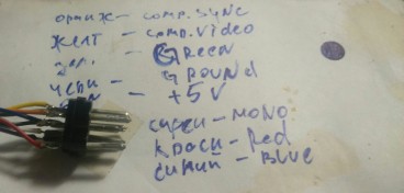
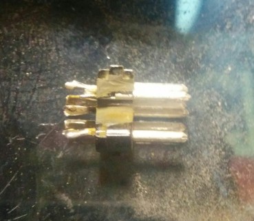
4. Спаиваем все провода и обозначаем за что отвечает каждый цвет
Пайка контактов производилась по схемам расположенным чуть ниже

5. Вставляем разъем в гнездо приставки , заливаем его и провода клеевым термопистолетом. После полного остывания клея, я прогрел остывшую массу феном (если нет фена, можно подержать наше творение над газовой плитой или над чем-то горячим), еще раз дождался полного застывания клея и только потом надел на коннектор кожух.

Вот в принципе и все, на фото ниже показано как выглядит конечный результат
Пройдя по ссылке (тынц) можно увидеть как меняется качество картинки при использавнии данного кабеля.

Хочу посвятить эту тему разоблачению популярного мифа. На Алиэксперсс, относительно давно появились кабели для Мега Драйв 1. Которые почему-то не подходили к приставке. Вставлялись в консоль или очень туго и не до конца, или вообще не вставлялись. После многочисленных жалоб некоторые продавцы начали выставлять картинки "пояснящие" такие косяки. Якобы у PAL консолей и NTSC, отличаются порты. C-Pin для PAL, и V-Pin для NTSC. Недобросовестные продавцы таким способом отсеяли клиентов, у которых были NTSC консоли. Отписывая им, что кабель не подходит потому, что у вас не PAL консоль.
И этот миф стал настолько популярен, что мне довольно часто задают вопрос, или уточняют - "Мне нужен кабель именно для PAL консоли, или именно для NTSC".
Есть предположение, что китайцы перед массовым производством кабелей, просто ошиблись с типом разъёма, и наштамповали C-Pin кабелей очень много. Это разъём Neo Geo. И девать то их некуда, а продавать надо. Вот они и начали их продавать с обманом.
В чем разница, в чем + последнего более дорогого?
Знаю что был случай дешевый китайский кабель с Али давал честную картинку RGB на моем старом ЭЛТ 29 Самсунге и черный экран на новой ЖК соньке был только звук. При чем второй аналогичный китайский кабель уже работал и на ЖК соньке. Может это как раз дело в тех синхронизациях?
Так же вопрос по RGB Scart к приставкам от нинтендо, если по N64 все понятно никакого RGB без мода от туда не получить то по SNES и Gamecube есть вопросы.
Как бы разъемы одинаковы, нативный RGB есть там и там. Но не раз попадал на кабеля что если хорошо работает на Gamecube, то очень темно на SNES или вовсе не работает и наоборот. В чем загвоздка здесь, есть ли универсальный RGB кабель для всех приставок Нинтендо, или нужно отдельно под каждую консольку и как отличить какой под какую?
Читайте также: