
Как включить poe на mikrotik 951g 2hnd
Обновлено: 05.07.2024
PoE-Out Configuration
PoE Configuration is supported on all MikroTik devices with PoE-Out interfaces, the configurations can be edited from the RouterOS and SwOS interfaces.
RouterOS
Usage
RouterOS provides an option to configure PoE-Out over Winbox, Webfig, and CLI, basic commands using the CLI are
| Property | Description |
|---|---|
| print () | Prints PoE-Out related settings. |
| export () | export is displayed under /interface ethernet menu. |
| monitor (string| interface) | Shows poe-out-status of a specified port, or all ports with /interface ethernet poe monitor [find] command. |
| power-cycle (time:0..1m |; Default: 5s) | Disables PoE-Out power for a specified period of time. |
Global Settings
Some MikroTik PoE-Out devices support the global PoE setting which can be configured under /interface ethernet poe settings menu. Global setting ether1-poe-in-long-cable feature disables strict input/output current monitoring (short detection) to allow the use of PoE-Out with long ethernet cables and/or avoiding improper short-circuit detection.
| Property | Description |
|---|---|
| ether1-poe-in-long-cable (yes | no) | Setting it to "yes" will disable short detection on all poe-out ports. This is potentially dangerous settings and should be used with caution |
Note: Global setting of ether1-poe-in-long-cable can also affect PoE-Out behavior on PSE which is powered using a DC connector
Port Settings
PoE-Out can be configured under the menu. Each port can be controlled independently.
- auto-on - the board will attempt to detect if power can be applied to the port. For power-on to happen there should be resistance on spare pairs in the range from 3kΩ to 26.5kΩ
- forced-on - detection range is removed. As a result power over Ethernet will be always on
- off - all detection and power is turned off for this port
Highest priority is 0, the lowest priority is 99. If there are 2 or more ports with the same priority then port with the smallest port number will have a higher priority. For example, if ether2 and ether3 have the same priority and over-current is detected then PoE-Out on ether3 will be turned off.
Power-cycle settings
RouterOS provides a possibility to monitor PD using a ping, and power-cycle a PoE-Out port when the host does not respond. power-cycle-ping feature can be enabled under /interface ethernet poe menu.
| Property | Description |
|---|---|
| power-cycle-ping-enabled (yes | no; Default: no) | Enables ping watchdog, power-cycles port if a host does not respond to ICMP or MAC-Telnet packets. |
| power-cycle-ping-address (IPv4 | IPv6 | MAC; Default: ) | An address which will be monitored. Since RouterOS 6.46beta16, an active route towards PD is required in case an IP address is configured, so make sure PSE can reach the PD. In case the MAC address is specified, PSE will send MAC-Telnet ping requests only from a specified ethernet interface. When configuring a bridge vlan-filtering or some way of VLAN switching, it is recommended to use the IP address for monitoring your PD. |
| power-cycle-ping-timeout (time:0..1h |; Default: 5s) | If the host does not respond for more than <timeout> period of time, then PoE-Out port is switched off for 5s. |
| power-cycle-interval (time| any; Default: ) | Disables PoE-Out power for 5s between the specified intervals. Not related with the power-cycle-ping feature. |
If power-cycle is enabled, /interface ethernet poe monitor will show the actual status of the host and time when power cycle will be performed [1]
SwOS interface provides basic PoE-Out configuration options:
- PoE Out - Change between PoE-out modes (auto/on/off)
- PoE Priority - Change the Priority of port (0. 8)
- Voltage Level - Change between two voltage outputs on PoE-Out ports (auto/low/high)
Troubleshooting
In cases where a PD does not power-up or reboots unexpectedly when powered from your PSE, it's suggested to the first check:
- PD supported input voltage - PSE output voltage must be in the range supported by the PD. Otherwise, the PD is incompatible with the PSE, and will not be able to power-up. Check the PD datasheet.
- PD supported input PoE-in standard - Some PDs do not support af/at standard even if it has PoE-in support up to 57 V, check PD datasheet.
- PD is rebooted from PSE
- Check if PD does not exceed PoE-Out port limit and Total-PoE-Out port limit of the PSE, check PSE datasheet.
- Check if the Voltage limit does not drop bellow supported (Can be caused by voltage drop on the wires).
- Check if you are using a proper power supply, the output power of PSU should be calculated from:
- Check if you are using good quality ethernet cables, it's important especially in cases if PoE is used.
- There can be cases where a PD does not power up, even though it supports passive PoE, and does not consume more power than the specified PSE port limit. This can be caused by inrush current triggering overcurrent protection on the PSE. Make sure that PD specification supports powering from PSE (not only from passive power injector)
- Polarity - Devices with opposite or different pinouts can be unable to powerup from all PSE. Check the PD datasheet.
- Incompatible resistance - PD resistance on spare pairs should have ranged from 3kΩ to 26.5kΩ (For Passive-PoE) and from 23.75kΩ to 26.25kΩ on af/at.
PoE-Out Monitoring
RouterOS
MikroTik devices with PoE-Out controller (not injector) provides port monitoring option. /interface ethernet poe monitor [find]
- powered-on - Power is applied to the port, and PoE-Out is operating normally,
- waiting-for-load - PSE attempts to detect if power can be applied to the port. For power-on to happen there should be resistance on spare pairs in the range from 3kΩ to 26.5kΩ;
- short-circuit - Short-circuit is detected on PoE-Out port, power is switched off, the only detection with low voltage takes place.
- overload - The PoE-Out current limit is exceeded, power is switched off on PoE-Out port. For port limits see each model specifications.
- voltage-too-low - PD can not be powered with the voltage provided from PSE.
- current-too-low - current-too-low means that PD draws too low current (<10mA) than normal PoE-Out device should, the reason for this can be:
The delivered voltage at PD is too low for normal powering (for example Vmin =>30V, but provided 24V);
PD uses a second power source which has a higher voltage than PSE, so all current is taken from the second DC source, not PSE PoE-Out port;
- off - all detection and power is turned off for this port;
If power-cycle-ping feature is used, /interface ethernet poe monitor [find] will show additional fields:
power-cycle-host-alive: <YES/NO> (Shows if monitored host is reachable)
power-cycle-after:<TIME> (Shows time, after which the port will be power-cycled)It is possible to monitor PoE-Out values using SNMP protocol, this requires enabled SNMP on PSE. SNMP Wiki
SNMP OID tables:
- 1.3.6.1.4.1.14988.1.1.15.1.1.1 - interface-id
- 1.3.6.1.4.1.14988.1.1.15.1.1.2 - interface names
- 1.3.6.1.4.1.14988.1.1.15.1.1.4 - voltage in dV (decivolt)
- 1.3.6.1.4.1.14988.1.1.15.1.1.5 - current in mA
- 1.3.6.1.4.1.14988.1.1.15.1.1.6 - power usage in dW (deviwatt)
SNMP values can be requested also from the RouterOS, for example, snmp-walk will print current mA from all available PoE-Out ports:
/tool snmp-walk address=10.155.149.252 oid=1.3.6.1.4.1.14988.1.1.15.1.1.5
To get very specific OID value, use snmp-get tool (displays current mA on ether3 interface):
tool snmp-get address=10.155.149.252 oid=1.3.6.1.4.1.14988.1.1.15.1.1.5.3
A PoE-Out controller will enable certain monitoring features also from SwOS, such as PoE-Out Status, PoE-Out Current, PoE-Out Voltage, and PoE-Out Power usage.
![]()
PoE Out examples
RouterOS allows us to define priorities on PoE-Out ports, so if your installation is going overpower budget, the PSE will disable less important PD with the lowest priority.
The priority of 0 is the highest priority, 99 - lowest
Setting up priority
Example of how to set priorities from CLI:
/interface ethernet poe set ether2 poe-priority=10
/interface ethernet poe set ether3 poe-priority=13
/interface ethernet poe set ether4 poe-priority=11
/interface ethernet poe set ether5 poe-priority=14What will happen when power budget will go over total PoE-Out limit - first if the overload is detected, ether5 will be turned off (lowest priority), then recheck is done and if the still total limit overload is detected next port in priority will be turned off, in this example, ether3 will be turned off. Both of these ports will be reached every few seconds to check if it is possible to turn PoE-Out on for these ports. Power up will happen in reverse order as the power was cut.
Same priority
if all, or some ports will have the same poe-priority, then port with the lowest port number will have higher priority
/interface ethernet poe set ether2 poe-priority=10
/interface ethernet poe set ether3 poe-priority=10
/interface ethernet poe set ether4 poe-priority=10
/interface ethernet poe set ether5 poe-priority=10In this example, if the total PoE-Out limit is reached ether5 will be turned off first, then ether4 then ether3 as all of these ports have same poe priority.
Monitoring PoE-Out
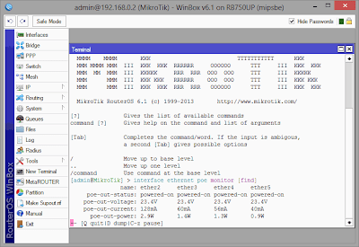
PoE-Out ports can be monitored using a command /interface ethernet poe monitor <interface>
[admin@MikroTik] > interface ethernet poe monitor [find]
name: ether2 ether3 ether4 ether5
poe-out-voltage: 23.2V 23.2V 23.2V
poe-out-current: 224mA 116mA 64mA
poe-out-power: 5.1W 2.6W 1.4WPower-cycle ping
/interface ethernet poe set ether1 power-cycle-ping-enabled=yes power-cycle-ping-address=192.168.88.10 power-cycle-ping-timeout=30s
In this example, PD attached to ether1 will be continuously monitored using a power-cycle-ping feature, which will send ICMP ping requests and wait for a reply. If PD with IP address 192.168.88.10 will not respond for more than 30s, the PoE-Out port will be switched off for 5s.
How it works
PoE-Out Modes
auto-on mode
If auto-on is selected on PoE-Out interface, then port operates in this strict order:
- PSE with low voltage checks for resistance on the connected port. If the detected resistance range is between (3kΩ to 26.5kΩ) power is turned on;
- When power is applied, the PSE continuously checks if the overload limit is not reached or short circuit detected
- If the cable is unplugged, the port returns in detection state and will remain off until suitable PD is detected
forced-on mode
If forced-on is selected then port operates in this strict order:
- PSE disables resistance check on the port, and apply power on pins 4,5 (+) and 7,8 (-), even if no cable is attached
- When power is applied, PSE still continuously checks if an overload or short circuit is not detected
- After the cable is unplugged, the power still remains enabled on the port.
off mode
If off mode is used, PoE-Out on the port will be turned off, no detection will take place, and the interface will behave like a simple Ethernet port.
PoE-Out limitations
It is important to check PoE-Out specification to find out hardware limitations because it can differ between models
PoE-Out port limitation
PoE-Out ports are limited with max amp values which are supported in particular voltage, usually max current will differ for low voltage devices (up to 30 V), and for high voltage devices (31 to 57 V).
PoE-Out total limitation
PSE has also a total PoE-Out current limitation which can't be exceeded, even if the individual port limit allows it.
PoE Out polarity
All MikroTik PSE uses the same PoE-Out pin polarity Mode B 4,5 (+) and 7,8 (-), however other vendors can use opposite or Mode A pinout on PD, this would require using a special crossover cable.
Note: Passive PD with high input inrush current can result in overcurrent protection on PSE, make sure that PD specification supports powering from PSE (not only from the passive power injector)
Safety
PSE has the following safety features:
PoE-Out compatibility detection
The auto-on mode is considered safe, it will check if the resistance on the port is within allowed range and only then enable PoE out on the interface. The range is 3kΩ to 26.5kΩ
Overload protection
When a PoE-Out port is powered-on, it is constantly checked for overload. If the overload is detected, PoE-Out is turned off on the port to avoid damage to the PD or PSE.
In seconds the PoE Out feature will be turned on again to see if the environment has changed and PD can be supplied with power again. That is important for configurations that are not connected to mains (solar installations, equipment running on batteries due to mains failure) so that when voltage drops - overload will be detected and connected devices turned off. After a while when the voltage level returns to usual operating value - connected equipment can be powered up again.
Short circuit detection
When power is enabled on PoE-Out port, PSE continuously checks for a short circuit. If it is detected to ensure that there is no additional damage to PD and PSE, the power is turned off on all ports. PSE will continue to check PoE-Out port until the environment returns to normal.
Warning: Make sure that non-standard incompatible PD which does not have the resistance range 3kΩ to 26.5kΩ are not attached, so the PSE would not try to apply power on them
Model-specific features
Legacy
PoE-Out Controller upgrade
PoE-Out devices which are running RouterOS 5.x can also hold old PoE-Out controller firmware, upgrade to RouterOS 6.x will automatically update the PoE-Out firmware. Changes between 1.x and 2.x PoE-Out controller firmware will result in higher Max-port limits (0.5A to 1A) in case if it's supported by the hardware, also will provide some additional data which can be monitored, and allow to use PoE-Out priorities.
All MikroTik devices which come with RouterOS 6.x already support the latest PoE-Out firmware.
Есть роутер Mikrotik 951G-2HnD, прошивка 6.43.7. WAN настроен на Ether1. Блок питания Mikrotik 24В.
Есть точка доступа Mikrotik wAP с комплектным пассивным PoE инжектором.
По мануалу в Mikrotik 951G-2HnD порт Ether1 - PoE input, Ether5 - PoE output.
Хочу запитать Mikrotik 951G-2HnD при помощи пассивного инжектора, а саму точку доступа от порта Ether5 роутера Mikrotik 951G-2HnD.![5c0be8aed9802867501433.jpg]()
В итоге - роутер запитался и работает нормально. Интернет есть.
Точка доступа питание не получает. Прочитал, что выход PoE нужно включить (хотя по мануалу - он должен быть в режиме Default: auto-on). В текущей прошивке не могу найти где включается. Команды в терминале про POE тоже не действуют.
Куда копать?![]()
Очень часто у нынешних «Системных администраторов», возникает проблема с настройкой 802.11 оборудования, попробую объяснить на доходчивом уровне.
В данном посте попробую рассказать, как настроить обычную точку доступа на оборудовании MikroTIk 751,951,2011 etc 802.11 b/g/n
Я приведу пример готовой настройки и расскажу только об основных настройках, так как в рамках одной стати сложно описать весь принцип работы и настройки 802.11.
Прошу не считать данный пост как догму.И так прежде чем настраивать MikroTik, я рекомендую, сбрось настройки WLAN.
Вкладка (Wireless)
![]()
Mode: — режим работы нашей карточки выбираем «ap bridge»Band: — Какие стандарты будут поддерживаться нашей точкой доступа, выбираем «2ghz-b/g/n»
SSID: — Тут всё просто, название нашей сети
Wireless Protocol: какие протоколы для работы будет использоваться наша точка, тут стоит указать только 802.11, так как мы не будем делать «Новогоднюю ёлку из нашей точки доступа», а просто обычная точка доступа.
Country: Выбираем нашу страну. Наверняка возникает вопрос, а зачем? Ответ: Законодательством разных стран, разрешены разные частоты, чтобы нам не получить аплеуху от РОСКОМНАДЗОР-а, MikroTik не даст нам возможности работать с другими частотами.
Antenna Gain: Если у вас есть внешняя антенна обязательно укажите её усиление, с расчётом -0,5, на соединительный узел. А также если вы используете кабель, посмотрите маркировку на кабеле, затухание на единицу измерения (метр, 10 метров etc) кабеля и введите значение с учётом затухания кабеля.
WMM Support: Если вы будите использовать Multicast, то установите эту опцию в Enabled, это даст большие гарантии на доставление этого пакета. Если вы настраиваете MikroTik дома то включите эту опцию, если же это ресторан или конференц зал, то сожрать весь канал может один клиент.
Вкладка (Data Rates)
![]()
Здесь всё просто
Rate Selection: выбираем Legaсy расширенная поддержка (для старых устройств), без этой опции старый баркодер не как не хотел ужиться с Mikrotik-омВкладка. (Advanced)
![]()
Distance: Очень интересный параметр, если клиенты находятся в одном помещении и примерно на одном расстоянии, ну допустим все в радиусе 20 метров от точки доступа то укажите indoors, если у вас открытая местность поле или конференц зал, и клиенты находятся на разных расстояниях более 0-20 метров то укажите значение dynamic. Ну и третье если клиенты находятся на одном расстоянии, допустим 1км, то так и укажите. Данная опция позволяет Mikrotik по вшитому алгоритму рассчитывать доставлен ли пакет до нужного адресата.Periodic Calibration: Дело в том, что чип WiFi во время свое работы греется, и из-за этого может частота съезжать немного, соответственно включите эту опцию. Следующее поле оставьте равным одной минуте. Будет происходить калибровка частоты каждую минуту.
![]()
Не хотел писать про этот пункт.
Hw. Protection Mode: Данный пункт может помочь в решении проблемы скрытого узла, если указать «rts cts».
Совсем кратко: 802.11 (он же вифи) – это единая среда передачи данных (Вспомните устройство ХАБ), а в стандарте 802.11 указанно, что клиенты сами определяют между собой, кто и когда будет производить запись, НО есть один нюанс это условие будет работать, только если клиенты видят друг друга напрямую. Если же два клиента начнут писать одновременно, то мы получаем коллизию.
Как пример представим себе некое поле (То которое на рабочем столе Windows XP).
На нём располагается точка доступа на рисунке красная точка, и её радиус бледно красным.
А также
Шрайбикус (A), Вася (B), Коля (С)
Шрайбикус и Вася могут быть нормальными участниками и работать в сети без сбоев, но, а вот из-за Коляна могут возникнуть проблемы у всех, дело в том, что Шрайбикус и Вася могут общаться напрямую и определять, кто из них будет вещать в данный промежуток времени. А вот Коля не видит не одного из участников нашей сети, и может смело вещать в любой момент даже в тот, когда Вася или Шрайбикус будут также вещать, из-за этого и появляются коллизии.Вернёмся к настройке MikroTik значение rts cts, если просто то «Точка доступа сама будет управлять, кому вещать в данный момент», что решит проблему скрытого узла. Данный параметр слегка снизит пропускную способность, и увеличит нагрузку на точку доступа. (Обязательный параметр)
Adaptive Noise Immunity: этот параметр позволяет чипу 802.11, отфильтровывать шумы, ну как пример отражённый сигнал самой точки доступа от соседнего здания. Установите значение равное “ap and client mode”
Вкладка (HT)
Здесь поставить только две галки
HT Tx Chains – Установить галки в chain0 и chain1HT Rx Chains – Установить галки в chain0 и chain1
У SOHO MikroTik обычно две встроенные антенны, соответственно данный параметр говорит через какие антенны принимать и передавать.
Вкладка (TX Power)
![]()
Большинство MIkroTik используют 1W передатчики, но по нашему законодательству, разрешено использовать точки доступа без регистрации не более 0.1W.
В вкратце усиление в 17 dBm – Примерно 0.1W увеличение на три пункта, увеличивает мощность передатчика вдвое.
И того:
18 dBm1W(по умолчанию обязательно убрать ) — Микроволновка ))))
Настоятельно рекомендую установить значение, равным 15 и если не будет хватать, то поднять не белее 17-19.
Собственно всё, мы почти закончили теперь нам необходимо выбрать канал (частоту) и ширину канала.
Именно на этом этапе чаще всего допускаю ошибки, поэтому оставил на конец.
И так откинем сразу шируну канала 5 и 10 MHz, так как половина домашнего оборудования на такой ширине работать не будет. В следующих постах расскажу, где можно использовать такую ширину.![]()
Нам доступен следующий диапазон 2412-2472, хитрым математическим анализом мы узнали, что нам доступна ширина в 60MHz.
Давайте посмотрим спектральный анализ всего диапазона.
[admin@test] /interface wireless> spectral-history wlan1 range=2412-2472
Мы видим, что для нас оптимальный вариант это частоты 2425-2445 (2437)Мы видим, что вроде всё хорошо, а теперь посмотри, кто и что сидят в эфире.
[admin@test] /interface wireless> scan wlan1
ADDRESS SSID BAND CHANNEL-WIDTH FREQ SIG NF SNR AP AC:F1:DF:26:29:60 sunchess 2ghz -n 20mhz 2412 -88 -115 27 AP 1C:AF:F7:28:55:32 Irisha 2ghz -n 20mhz 2412 -45 -115 70 AP 54:E6:FC:CD:4D:70 PAL 2ghz -n 20mhz 2417 -87 -116 29 AP 26:FF:3F:46:1B:74 InterZet-107 2ghz -n 20mhz 2417 -82 -116 34 AP A0:21:B7:BC:91:1A 2ghz -n 20mhz 2422 -82 -117 35 AP 90:F6:52:99:AB:F4 Igor 2ghz -n 20mhz 2432 -62 -118 56 AP 90:F6:52:C8:F2:30 TP-LINK_C8F230 2ghz -n 20mhz 2437 -78 -118 40 P 00:21:27:E9:C5:C4 SeRgey-Net 2ghz -n 20mhz 2437 -89 -118 29 AP DE:71:44:4F:44:73 DIRECT-hB[TV]UE32ES6307 2ghz -n 20mhz 2437 -79 -118 39 AP 00:14:D1:3B:5C:B3 TRENDnet 2ghz -n 20mhz 2437 -76 -118 42 P A0:F3:C1:84:C2:CA Nos_FamilyNet 2ghz -n 20mhz 2442 -90 -117 27 AP F8:D1:11:43:94:00 iz-gw-48312-160 2ghz -n 20mhz 2452 -74 -116 42 AP B8:A3:86:1F:C3:AE nasha 2ghz -n 20mhz 2457 -54 -116 62 AP 90:A4:DE:5C:1D:95 Connectify-me 2ghz -n 20mhz 2462 -72 -117 45 AP 54:04:A6:C6:AC:94 ASUS 2ghz -n 20mhz 2462 -58 -117 59 00:00:00:00:64:00 \AC\02\02\00\00\0F\AC\04\… 2ghz -n 20mhz 2472 -89 -117 28 P BC:F6:85:3F:2A:9A Dimitrakis 2ghz -n 20mhz 2437 -91 -118 27 AP E0:91:F5:E7:D8:72 bui_family 2ghz -n 20mhz 2437 -90 -118 28
В данном выводе меня смутил одни товарищ, который выделен, название очень смахивает на телевизор, если на телике смотрят видео, а не телетекст то на этом канале мы можем попрощаться с нормальной работой WIFI, так как мультикаст и потоковое видео будет занимать весь свободный канал. (поживём увидим)
В нашем случае оптимальный канал это 2437. мы будем делить канал между 2427-2447.Ширина канала выбирается просто, если у нас во всём диапазоне всего пару точек, и всё они без каких, либо косяков, что-то вроде мультикаста и т.п.д.
Каналы 2412-2457 можно использовать как Above
Каналы 2432-2472 можно использовать как Below
Но такую ширину использовать только, когда действительно у вас частота чистая.Также стоит ещё раз напомнить, что WIFI это единая среда передачи данных. Если вдруг на тех же частотах(2452-2472), появится клиент с 802.11 g, то все участники этой частоты, будут работать со скоростью, что и наш клиент со старенькой карточкой.
1. Как работает PoE в микротиках? По какому протоколу? У микротиков "свой" PoE не совместимый со стандартом 802.3af. В документации это называется "Passive PoE. Non 802.3af". Используются ДВЕ ПАРЫ - синяя и коричневая. Синяя - Плюс. коричневая - Минус.
2. Какие ограничения на порт по питанию? из вики - "max limit on port - 1A, total limit - 2.2A"
4. При процедуре обновления, помимо обновления самой системы и загрузчика, на данных устройствах также необходимо выполнить обновления микропрограммы PoE. Выполняется командой
/interface ethernet poe settings upgrade
(внимание! из официальной википедии - "Warning: When updated to newer PoE-Out controller firmware version it is not possible to downgrade it", невозможно понизить версию прошивки PoE)5. Просмотреть текущее состояние PoE можно командой
interface ethernet poe monitor [find]![]()
6. Основные параметры PoE
auto-on - Роутер пытается определить требуется ли подавать питание или нет. Проверяет сопротивление на парах ( 3kΩ to 26.5kΩ) и если его нет, то подаёт.
forced-on - отключено тестирование по сопротивлению. В результате PoE включено всегда. (хотя после обновления, он в любом случае проверяет, даже при данном параметре)
off - все проверки отключены и питание на порт не подаётся..6. Приоритет - выставляется параметром poe-priority. Чем меньше число, тем выше приоритет
/interface ethernet poe set ether2 poe-priority=10
/interface ethernet poe set ether3 poe-priority=13
/interface ethernet poe set ether4 poe-priority=11
/interface ethernet poe set ether5 poe-priority=14
В данном примере, при проблемах с питанием (перегрузка, проблемы со входным питанием (к примеру при переключении на работу от ИБП)), вначале отключиться ether5, как имеющий наибольшее значение poe-priority. Затем будет отключен ether3, затем ether4. И только в самом конце ether2. Это может пригодиться к примеру, если подключены коммутаторы офисных компьютеров и серверов, а работа серверов важнее и мы гасим автоматом офисный коммутатор. Или постепенное отключение Wifi-точек доступа не являющихся критичными.
Если параметр poe-priority не указан или у всех указан одинаковый, то отключаться будет последовательно начиная с последнего порта (вначале ether5, затем ether4 и так далее)7. Для чего используется параметр ether1-poe-in-long-cable? - фраза с официальной вики "setting to yes will disable short detection on all poe-out ports to enable use of longer ethernet cables. This is potentially dangerous settings and should be used with caution.". Данный параметр отключает проверку на короткое замыкание в линии НА ВСЕХ OUT-портах, что позволяет использовать более длинные кабели. Это потенциально опасная настройка и использовать её надо осторожно.
Правда мне данный параметр непонятен. В тестах, на 90 метровом куске кабеля, 750UP смог поднять 951G-2HnD. Может пригодится если больше длина или менее качественный кабель используется.
![]()
C использованием высокочастотных трансформаторов на обоих концах линии с центральным отводом от обмоток постоянное напряжение питания подается на центральные отводы вторичных обмоток этих трансформаторов, и так же с центральных отводов снимается на приемной стороне. Использование центральных отводов сигнальных трансформаторов позволяет без взаимного влияния передавать питание по сигнальным парам, то есть передавать по одним и тем же проводникам и высокочастотные данные, и постоянное напряжение питания.
11. Можно ли сжечь оборудование, которое не поддерживает Passive PoE, подключив его к микротику выдающему питание по PPoE? Да можно. Passive PoE в режиме forced-on, по сути, банально использует синюю и коричневую пары для питания (Синий +, Коричневый -). Хотя в версии прошивки PoE выше 2.0 и на режиме forced-on выполняется проверка, но риск сжечь устройство (или отдельный порт, всё равно сохраняется)PS: ВНИМАТЕЛЬНО ПРОВЕРЯЙТЕ КАБЕЛЬ. НИ В КОЕМ СЛУЧАЕ НЕ ИСПОЛЬЗУЙТЕ ПРИ РАБОТЕ С PoE ОМЕДНЁННЫЙ. ТОЛЬКО ЧИСТУЮ МЕДЬ. Узнать кабель, который использовать нельзя можно по маркировкам - CCA, CA, CCS. (да и вообще никогда не используйте омеднёный кабель)
PoE-Out notifications
PoE-Out LEDs
Models with dependant voltage output
PoE-Out LED behavior can differ between models, but most of them will indicate PoE-Out state on one additional LED. Devices with one voltage output will light:
- Red color LED - PoE-Out port state is powered-on (auto or forced-on mode).
- Blinking Red color LED - PoE-Out port state is short-circuit
Models with selectable voltage output
Models with multiple voltage options can indicate additional information:
- Green color triangle LED - PoE-Out port state is powered-on (auto or forced-on mode), PD uses low voltage.
- Red color triangle LED - PoE-Out port state is powered-on (auto or forced-on mode), PD uses high voltage (af/at or passive).
- Blinking Green color triangle LED - PoE-Out port state (low voltage) is short-circuit or overload
- Blinking Red color triangle LED - PoE-Out port state (high voltage) is short-circuit or overload
Model-specific LED behavior
-
- All PoE LEDs flashing: wrong voltage PSU plugged into one of the ports.
- netPower 16P - All PoE LEDs flashing: wrong voltage PSU plugged into one of the ports. - indicates an exceeded overall max PoE output limit. Port PoE-Out priorities will work in 3 independent sections (8 ports each) and overload will happen in any section that breaches 150W consumption.


PoE-Out Logs
By default PoE-Out, event logging is enabled and uses "warning" and "info" topics to notify the user about PoE-Out state changes. Log entries will be added to each PoE-Out state change. Important logs will be added with a "warning" topic, informative logs will be added with the "info" topic.
To avoid unnecessary logging in cases when PD is not powered because of current-too-low, RouterOS will filter such events, and add one log per every 512 current-too-low events.
Logs can be disabled if necessary:
/system logging set [find topics
"info"] topics=info,!poe-out
/system logging set [find topics
PoE-Out Warnings in GUI/CLI
To notify a user about important PoE-Out related problems, messages will be shown in Winbox / WebFig and CLI interface fields:
1 RS ;;; poe-out status: overload
ether1 ether 1500 1588 9204 64:D1:54:61:D5:E0
WebFig and Winbox will notify user under interfaces:

MikroTik supported PoE-Out standards
MikroTik devices can support some or all of the following PoE standards:
- Passive PoE-Out up to 30 V - PoE standard, which does not require negotiation between PSE (Power Sourcing Equipment) and PD (Powered Device). PoE-out uses the same voltage as supplied to the PSE (Power Sourcing Equipment). PoE-Out Standard for devices that supports input voltage up to 30 V. PD resistance on spare pairs should have ranged from 3kΩ to 26.5kΩ. (e.g. hEX PoE lite, RB3011UiAS-RM, RB2011iL-IN.)
- Passive PoE-Out up to 57 V - Works the same as low voltage (up to 30 V) PoE-Out, but is also capable to deliver high voltage over PoE ports. The output voltage depends on the power source connected to PSE. Can power up af/at compatible devices, which accepts power over 4,5 (+) and 7,8 (-), and does not require PoE negotiation. PD resistance on spare pairs should have ranged from 3kΩ to 26.5kΩ. (e.g. cAP ac, hAP ac, wsAP ac lite.)
Each PoE-Out implementation supports overload and short-circuits detection.
Читайте также: